NAVFAC Oceana Runway 14L-32R
NAVFAC Oceana Runway 14L-32R
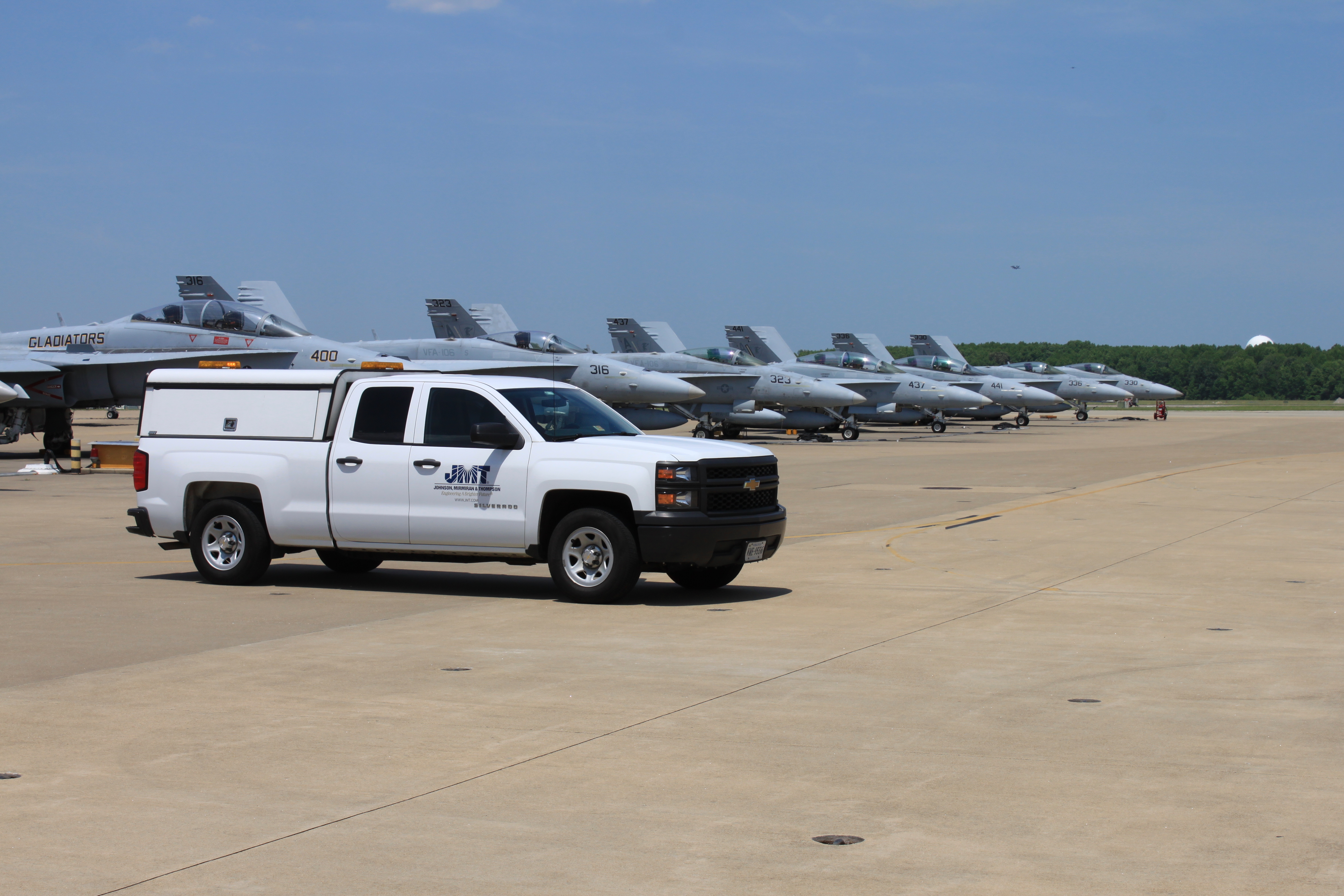
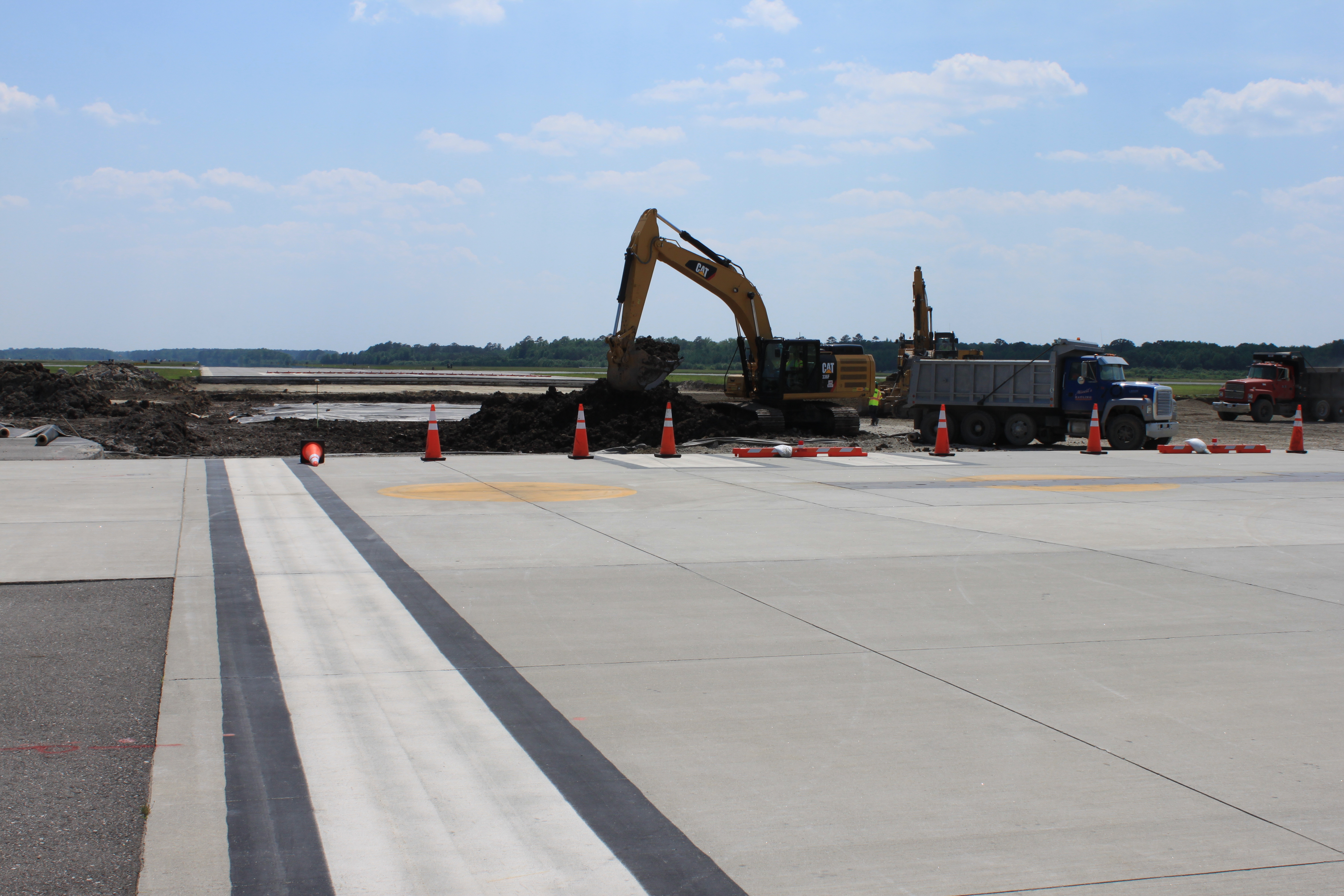
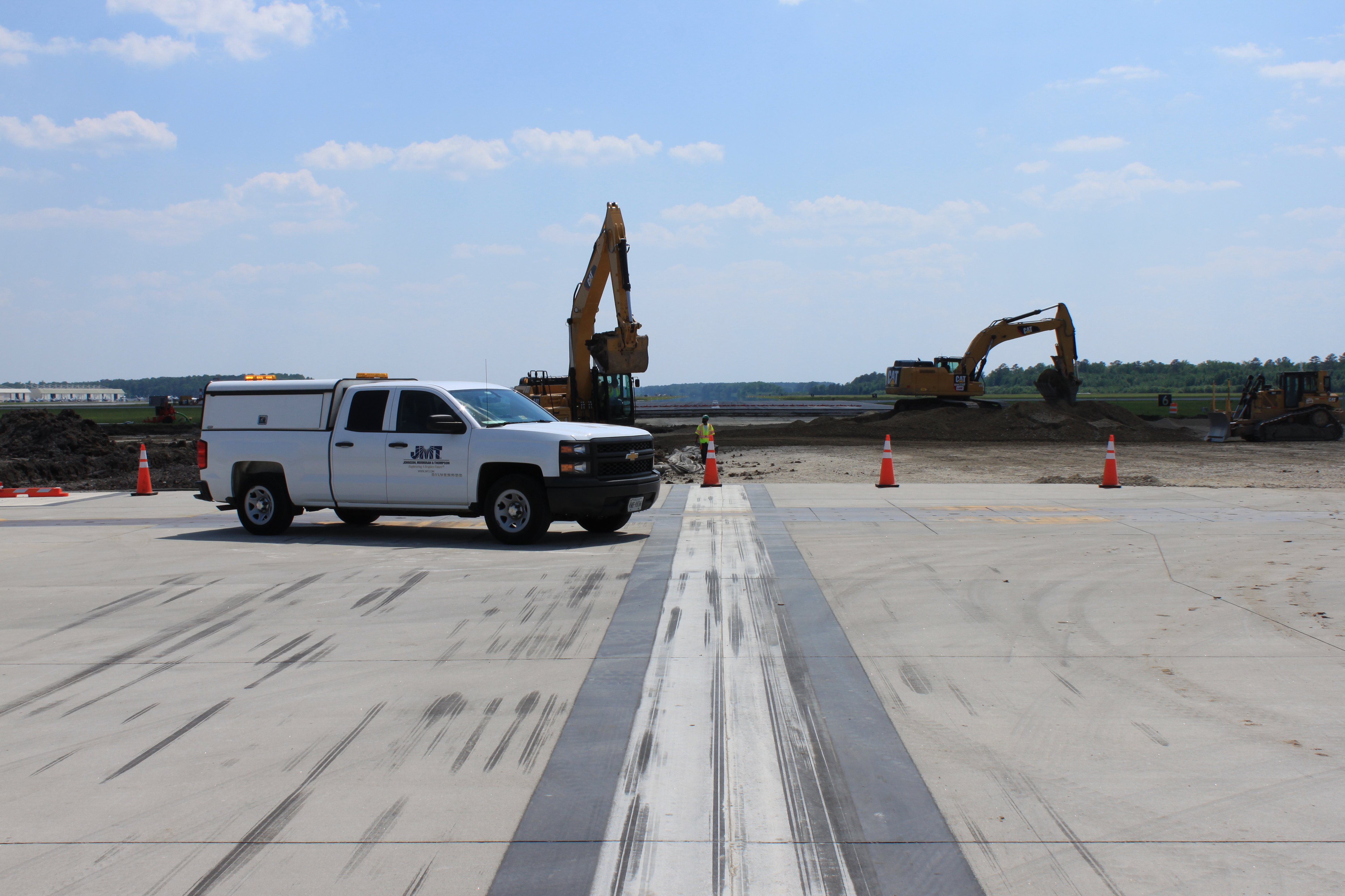
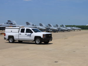
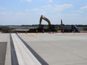
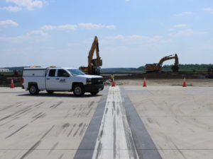
JMT designed the rehabilitation of Runway 14L-32R, one of four runways at Naval Air Station Oceana. The runway design included complete pavement demolition and reconstruction, with on-site concrete crushing for material re-use and provision for an on-site batch plant.
The design team also completed a second assignment for the modernization of electrical infrastructure airfield-wide, which changed the incandescent airfield lighting with new LED technology. The lighting design replaced circa 1940s handholes, ductbanks, and wiring, and provided two new lighting vaults, the renovation of two additional vaults, and conversion of an existing radar building to function as a fifth lighting vault. The design included runway and taxiway edge and centerline lights, apron and fuel pit lighting, threshold, hold short and obstruction lighting, airfield signage, lighted wind cones, electrical transformers, standby generators and constant current regulators, and airport lighting control and monitoring system (ALCMS). Edge lights were interleaved for reliability and new four-foot-wide shoulders for improved protection and maintenance were provided.
The team analyzed the effect of the 100-year storm to prevent runway flooding. The design addressed post-design impervious area conditions in compliance with the Virginia Runoff Reduction Method. Detailed site investigations were conducted, including pavement condition surveys for runway replacement, airfield-wide aerial survey, subsurface utility location, and inventory of electrical infrastructure.
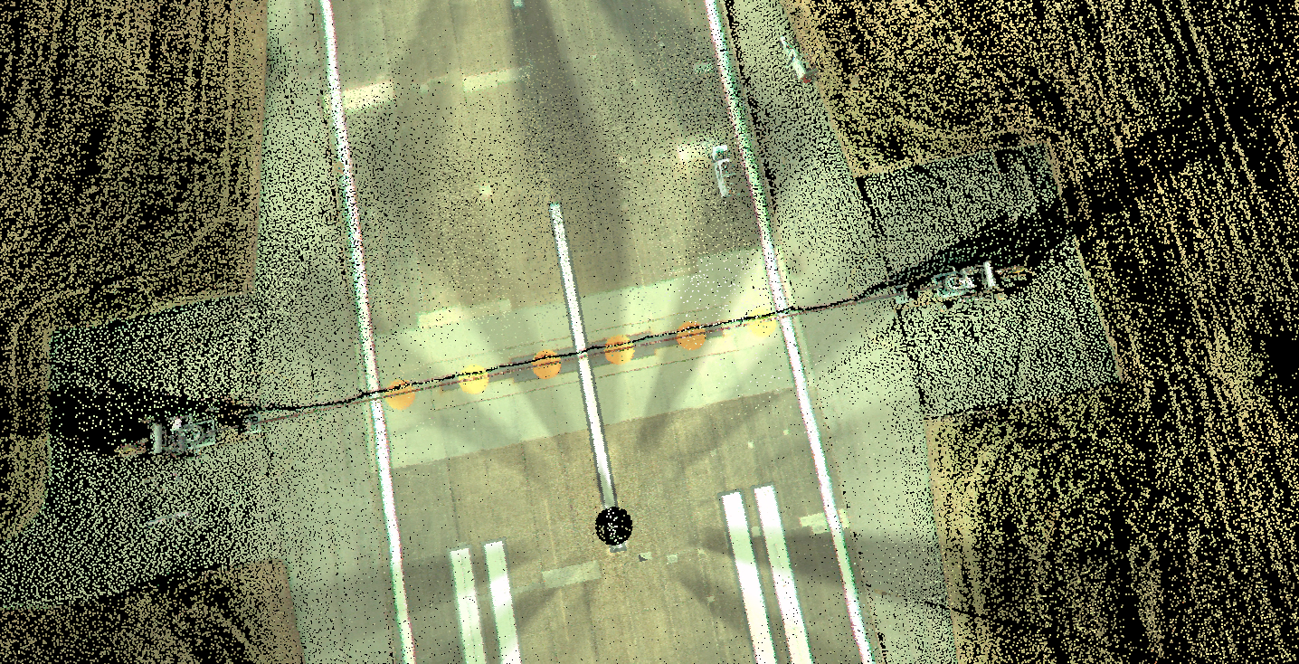
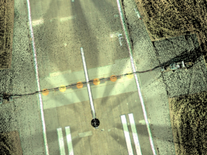
High definition aerial survey, or LiDAR, was used to save significant time and money. Once the aerial survey was completed, field crews surveyed the underground. Both sets of survey information were merged to create the existing conditions base map. The aerial survey provided an extreme amount of data used to create a detailed 3D surface that was used as the basis for the proposed design.
JMT’s engineers used AutoCAD 3D and its surface and terrain features to build the proposed design/surface from the existing surface. Once typical sections were added to the proposed surface, a large amount of information was generated, such as cut and fill limits and quantities, proposed contours, limits of disturbance, runway section quantities. All this information was dynamic and would update with any changes to the centerline alignment. This saved a considerable amount of time in completing the projects.